Kia Rio: Lighting System / Rheostat
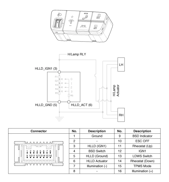
Components and components location
| Components |
Repair procedures
| Removal |
| 1. |
Disconnect the negative (-) battery terminal. |
| 2. |
Remove the crash pad lower panel. (Refer to Body - "Crash Pad Lower Panel") |
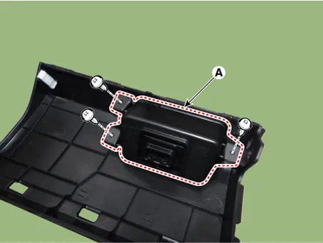
| 3. |
Remove the crash pad side switch (A) after loosening the mounting screws.
|
| Installation |
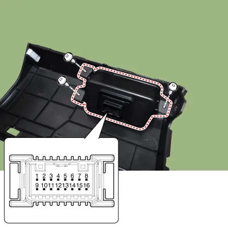
| 1. |
Install the crash pad side switch. |
| 2. |
Install the crash pad lower panel. |
| 3. |
Connect the negative (-) battery terminal. |
| Inspection |
| 1. |
Check for intensity of new rheostat switch. If the light intensity of the lamps changes smoothly without any flickering when the rheostat is turned, it can be assumed that the rheostat is normal.
|
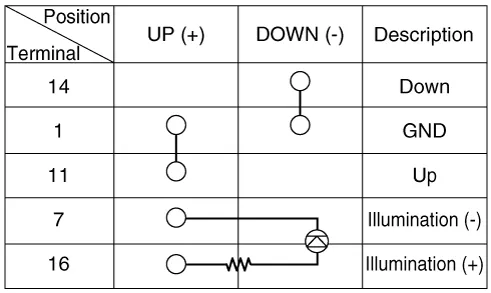
Repair procedures Inspection 1. Check for continuity between terminals. If the continuity is not as specified, replace the hazard lamp switch.
Repair procedures Removal 1. Disconnect the negative (-) battery terminal. 2. Remove the front bumper assembly.
Other information:
Kia Rio 2017-2023 YB Service Manual: Horn
Components and components location Component Location 1. Horn switch 2. Horn relay 3. Horn 4. Clock spring Repair procedures Removal 1. Remove the front bumper assembly.
Kia Rio 2017-2023 YB Service Manual: Heater Unit
Components and components location Component Location Components 1. Heater pipe cover 2. Heater core 3. Mode control actuator 4. Mode control actuator bracket 5. Mode control main lever 6.
Categories
- Manuals Home
- Kia Rio Owners Manual
- Kia Rio Service Manual
- Engine Electrical System
- Emission Control System
- Heating,Ventilation, Air Conditioning
- New on site
- Most important about car
