Kia Rio: Power Door Locks / Power Door Lock Module
Components and components location
| Components |

| 1. Door lock/unlock knob cable
|
2. Door latch assembly |
Repair procedures
| Inspection |
|

Front Door Lock Module Inspection
| 1. |
Remove the front door trim. (Refer to Body - "Front Door Trim") |
| 2. |
Remove the front door trim seal. (Refer to Body - "Front Door Window Glass") |
| 3. |
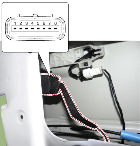
Disconnect the connector from the actuator.
[Central Lock Motor]
[Dead Lock Motor]
|
||||||||||||||||||||||||||||||||||||||||||||||||||||||||||
| 4. |
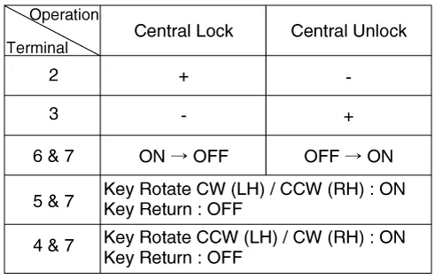
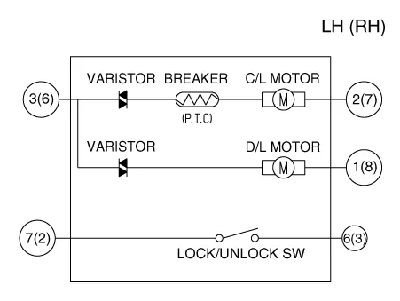
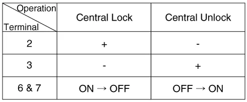
Check actuator operation by connecting power and ground as shown below. To prevent damage to the actuator, apply battery voltage only momentarily. [Central Lock Motor]
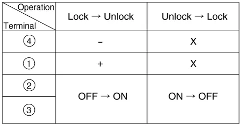
[Dead Lock Motor]
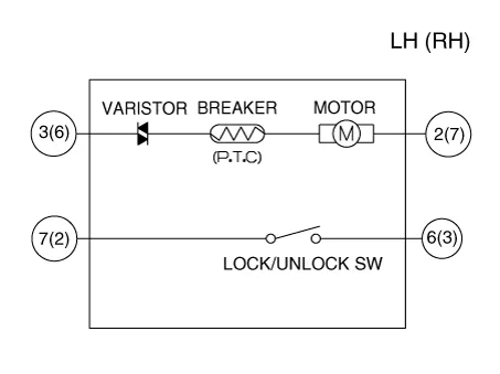
[Central Lock Motor] (LH)
(RH)
[Dead Lock Motor]
|


Rear Door Lock Module Inspection
| 1. |
Remove the rear door trim. (Refer to Body - "Rear Door Trim") |
| 2. |
Remove the rear door trim seal. (Refer to Body - "Rear Door Window Glass") |
| 3. |
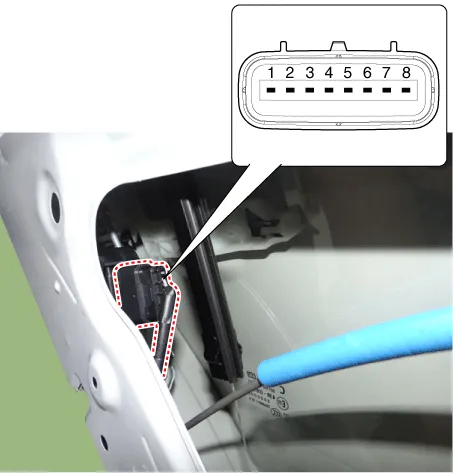
Disconnect the connector from the actuator.
[Central Lock Motor]
[Dead Lock Motor]
|
||||||||||||||||||||||||||||||||||||||||||||||||||||||||||
| 4. |
Check actuator operation by connecting power and ground as shown below. To prevent damage to the actuator, apply battery voltage only momentarily. [Central Lock Motor]
[Dead Lock Motor]
[Central Lock Motor] (LH)
(RH)
[Dead Lock Motor]
|


Tailgate Lock Module Inspection
| 1. |
Remove the tailgate trim. (Refer to Body - "Tailgate Trim") |
| 2. |
Disconnect the connectors from the actuator.
|

| 3. |
Check actuator operation by connecting power and ground as shown below. To prevent damage to the actuator, apply battery voltage only momentarily.
|

| 4. |
Checking the tailgate of the vehicle power option power refers to the tailgate module. |
Components and components location Component Location 1. Driver power window switch 2. Assist power window switch 3 .
Repair procedures Removal • When removing with a flat-tip screwdriver or remover, wrap protective tape around the tools to prevent damage to components.
Other information:
Kia Rio 2017-2023 YB Service Manual: Lighting System
Specifications Specification Item Type Bulb Watt (W) Front Headlamp Halogen Low/High H4 LL 55/60 Turn signal lamp PY21W 21 Position lamp W5W
Kia Rio 2017-2023 YB Service Manual: Rear Parking Assist System
Specifications Specification Item Specification Ultrasonic sensor Voltage rating DC 12V Detecting range 11.8 - 47.2 in (30 - 120 cm) Operation voltage DC 9 - 16 V Operation current
Categories
- Manuals Home
- Kia Rio Owners Manual
- Kia Rio Service Manual
- Filler-Neck Assembly
- Heating,Ventilation, Air Conditioning
- Suspension System
- New on site
- Most important about car
