Kia Rio: Brake System / Brake Pedal
Components and components location
| Components |
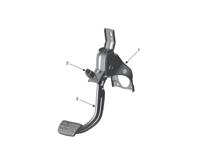
| 1. Brake member assembly 2. Stop lamp switch |
3. Pedal assembly |
Repair procedures
| Removal |
| 1. |
Switch "OFF" ignition and disconnect the negative (-) battery terminal. |
| 2. |
Remove the crash pad lower panel. (Refer to Body - "Crash Pad Lower Panel") |
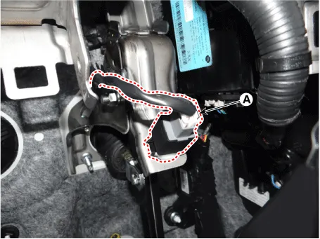
| 3. |
Disconnect the brake switch connector (A).
|
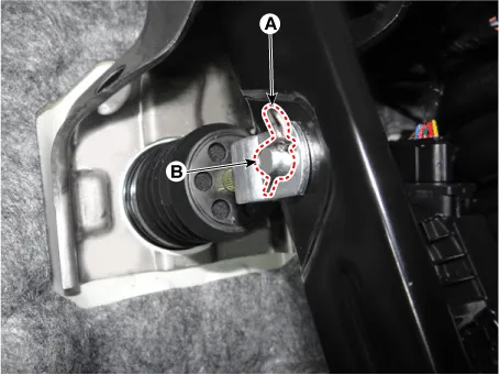
| 4. |
Disconnect the snap pin (A) and clevis pin (B).
|
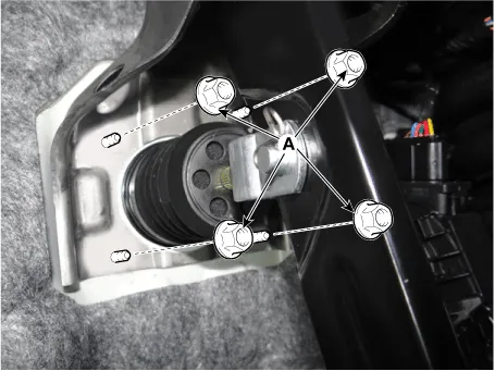
| 5. |
Remove the brake pedal mounting nuts (A).
|
| Inspection |
| 1. |
Check the bushing for wear. |
| 2. |
Check the brake pedal for bending or twisting. |
| 3. |
Check the brake pedal return spring for damage. |
| Installation |
| 1. |
Install in the reverse order of removal |
Components and components location Components Repair procedures Removal 1. Disconnect the brake fluid level switch connector (A) and then remove the reservoir cap.
Components and components location Components 1. Caliper body 2. Caliper carrier 3. Brake pad assembly [IN] 4.
Other information:
Kia Rio 2017-2023 YB Service Manual: Smart Key Diagnostic
Repair procedures Inspection Self Diagnosis With Scan Tool It will be able to diagnose defects of SMART KEY system with KDS/GDS quickly. KDS/GDS can operates actuator forcefully, input/output value monitoring and self diagnosis. The following three features will be major problem in SMART KEY system.
Kia Rio 2017-2023 YB Service Manual: Evaporator Temperature Sensor
Description and operation Description The evaporator temperature sensor will detect the evaporator core temperature and interrupt compressor relay power in order to prevent evaporator freezing by excessive cooling. Repair procedures Inspection 1.
Categories
- Manuals Home
- Kia Rio Owners Manual
- Kia Rio Service Manual
- Engine Mechanical System
- Maintenance
- Steering System
- New on site
- Most important about car
