Kia Rio: Button Engine Start System / Start/Stop Button
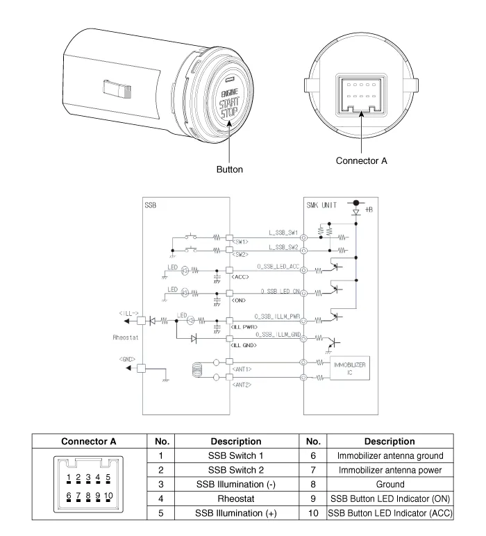
Components and components location
| Component |
Repair procedures
| Removal |
| 1. |
Disconnect the negative (-) battery terminal. |
| 2. |
Remove the crash pad center lower panel. (Refer to Body - "Crash Pad Center Panel") |
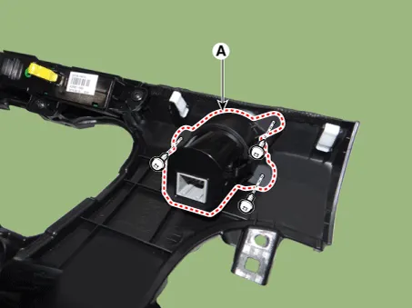
| 3. |
Remove the start/stop button (A) after loosening the mounting screws.
|
| Installation |
| 1. |
Install the start/stop button. |
| 2. |
Install the crash pad center lower panel. |
| 3. |
Connect the negative (-) battery terminal. |
Components and components location Component Location 1. Body control module (BCM) 2. Smart key unit (SMK) 3. Interior antenna 1 4.
Components and components location Component Repair procedures Removal 1. Disconnect the negative(-) battery terminal.
Other information:
Kia Rio 2017-2023 YB Service Manual: Compressor
Description and operation Description The compressor is the power unit of the A/C system. It is located on the side of engine block and driven by a V-belt of engine. The compressor changes the low pressure and low temperature refrigerant gas into the high pressure and high temperature refrigerant gas.
Kia Rio 2017-2023 YB Service Manual: Heater & A/C Control Unit (FATC)
Components and components location Components Connector Pin Function No. Connector A Connector B 1 Battery ⁻ 2 ISG battery (+) ⁻ 3 Illumination (+) ⁻
Categories
- Manuals Home
- Kia Rio Owners Manual
- Kia Rio Service Manual
- General Information
- Maintenance
- Coolant
- New on site
- Most important about car
