Kia Rio: Engine And Transaxle Assembly / Engine And Transaxle Assembly
Repair procedures
| Removal |
|

|

| 1. |
Remove the engine cover. (Refer to Engine And Transaxle Assembly - "Engine Cover") |
| 2. |
Remove the air cleaner assembly. (Refer to Intake and Exhaust System - "Air Cleaner") |
| 3. |
Remove the battery and battery tray. (Refer to Engine Electrical System - "Battery") |
| 4. |
Remove the engine room under cover. (Refer to Engine and Transaxle Assembly - "Engine Room Under Cover") |
| 5. |
Drain the engine coolant. (Refer to Cooling System - "Coolant") |
| 6. |
Recover the refrigerant and then disconnect the suction line and discharge line from the compressor. (Refer to Heating, Ventilation Air conditioning - "Compressor") |
| 7. |
Remove the transaxle wire harness connectors and control cable from the transaxle. (Refer to Manual Transaxle System - "Manual transaxle") |
| 8. |
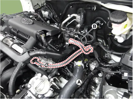
Disconnect the fuel hose (A), purge control solenoid valve (PCSV) hose (B).
|
| 9. |
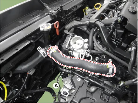
Disconnect the radiator upper hose (A).
|
| 10. |
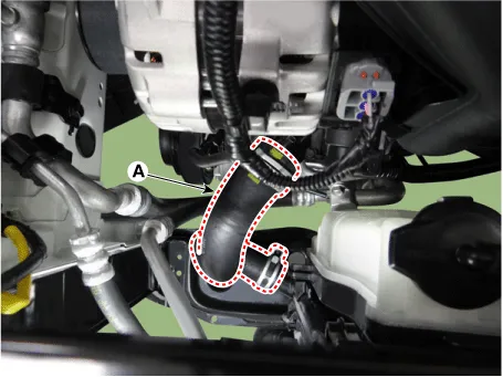
Disconnect the radiator lower hose (A).
|
| 11. |
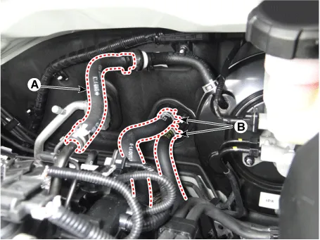
Disconnect the brake booster vacuum hose (A) and heater hoses (B).
|
| 12. |
Disconnect the automatic transaxle fluid (ATF) cooler hoses. (A/T only)
|
| 13. |
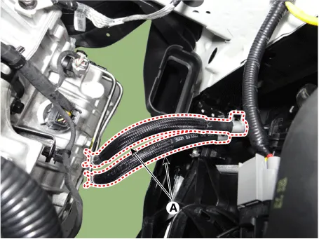
Disconnect the control wiring harness connectors and fasteners and remove the wiring harness protectors from the engine and transaxle.
|
| 14. |
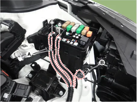
Disconnect the fuse box wiring cable (A) and front connector (B).
|
| 15. |
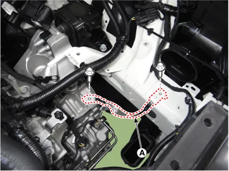
Disconnect the transaxle ground cable (A).
|
| 16. |
Remove the front muffler. (Refer to Intake And Exhaust System - "Muffler") |
| 17. |
Remove the roll rod bracket (A).
|
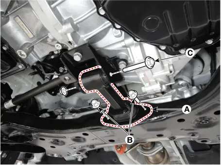
| 18. |
Remove the roll rod mounting support bracket (A).
|
| 19. |
Remove the sub frame. (Refer to Suspension system - "Sub frame") |
| 20. |
Support the engine and transaxle assembly with a lift table. |
| 21. |
Disconnect the engine ground cable (A).
|
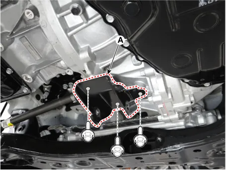
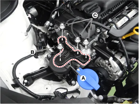
| 22. |
Remove the engine mounting support bracket (A).
|
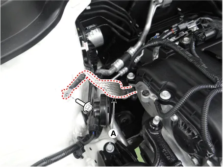
| 23. |
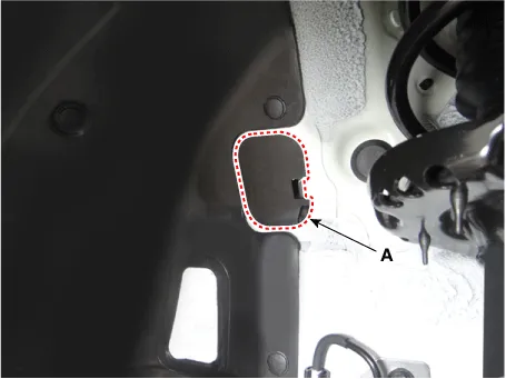
Remove the service cover (A).
|
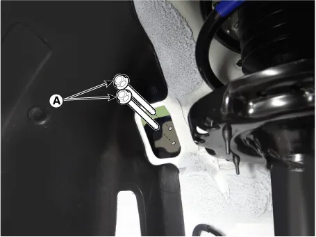
| 24. |
Remove the transaxle mounting bolts (A).
|
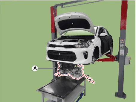
| 25. |
Remove the engine and transaxle assembly (A) by lifting vehicle.
|
| Installation |
Install the other parts in reverse order of removal.
Perform the following :
| • |
Adjust a shift cable. |
| • |
Refill engine with engine oil. |
| • |
Refill a transaxle with fluid. |
| • |
Refill a radiator and a reservoir tank with engine coolant. |
| • |
Place a heater control knob on "HOT" position. |
| • |
Clean battery posts and cable terminals and assemble. |
| • |
Inspect for fuel leakage. |
| – |
After assemble the fuel line, turn on the ignition switch (do not operate the starter) so that the fuel pump runs for approximately two seconds and fuel line pressurizes. |
| – |
Repeat this operation two or three times, then check for fuel leakage at any point in the fuel line. |
| • |
Bleed air from the cooling system. |
| – |
Start engine and let it run until it warms up. (until the radiator fan operates 3 or 4 times.) |
| – |
Turn Off the engine. Check the level in the radiator, add coolant if needed. This will allow trapped air to be removed from the cooling system. |
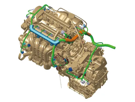
Components and components location Components 1. Engine mounting bracket 2. Engine mounting support bracket 3.
Other information:
Kia Rio 2017-2023 YB Service Manual: Rear Parking Assist System
Specifications Specification Item Specification Ultrasonic sensor Voltage rating DC 12V Detecting range 11.8 - 47.2 in (30 - 120 cm) Operation voltage DC 9 - 16 V Operation current
Kia Rio 2017-2023 YB Service Manual: Blower Unit
Components and components location Component Location Components 1. Intake actuator 2. Air filter 3. Air filter cover 4. Resistor 5. Mosfet 6. Intake seal 7. Intake upper cover 8.
Categories
- Manuals Home
- Kia Rio Owners Manual
- Kia Rio Service Manual
- Suspension System
- Cooling System
- Body (Interior and Exterior)
- New on site
- Most important about car
